
Touch screen and encoders
The display area is divided in four parts:
At the top side there are the menu buttons, the middle area in splitted in two squares for each VFO. In the bottom side there are the panel indicators for eight encoders.
Using a short click on each button (yellow highlighted rectangle) you can select menus and activate VFO A or VFO B. A short click in the red rectangle is used to set the transmission frequency
(useful for split operations).
A yellow rectangle highlights the active slice. You must activate a slice before changing its frequency or any other settings.
The device is perfectly synchronized with SMART-SDR therefore any changes made with SmartSDR is reflected in the Flex Controller and viceversa.
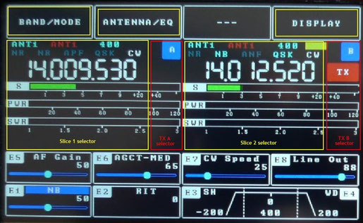
A long click on the two slice rectangles enable (start) or disable the related receiver. In the picture below the receiver B has been deactivated (closed).

Encoders
Encoders are numbered from 1 to 8 as in the picture below. For each encoder is reserved an area with a label that has the same encoder's name.
Each panel indicates the name of the current control set, its value and a slider with the position corresponding to the actual encoder value.

A short click on the encoder knob allows you to change the current function, while a long pression on the knob allows you to enable or disable the control (only when it is expected).
Below there is the full function list for each encoder/mode combination.

Here are some encoder's panel snapshots. When a control is activated its label is colored with a blue backgroung, while other controls are red colored when the related control is disabled.
In the example below the AF Gain and Headphone Gain controls are disabled while RIT control is enabled.

Filter bandwidth
Encoders E3 and E4 are dedicated to the filter bandwidth function. They works in couple: a click on E3 or E4 allows you to select SHIFT/WIDTH controls and another click let you switch back to the
HIGH/LOW controls.
A longer click allows you to normalize the filter bandwidth depending on the current selected mode. Default values are shown below:
| Mode | Bandwidth |
| CW |
-200/200 Hz |
|
USB |
100/2500 Hz |
|
LSB |
-2550/-100 Hz |
|
AM |
-3000/3000 |
|
DIGL |
-2250/-750 |
|
DIGU |
750/2250 |