
ESP32s Prosistel "D" remote control system
New! March 25th - 2024
Due to the difficulty in finding the NODEMCU-ESP8266 board I developed a new version of the program that can be installed on a more common and powerful ESP32s.
In respect with the previous version, the TCP/IP connector will no longer be available so, if you need to control the rotor via the serial port, you will need an hardware serial switch.
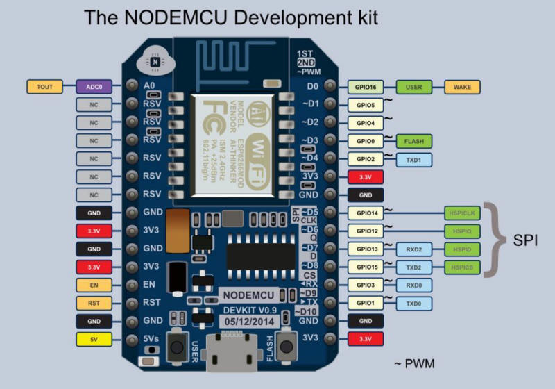
NOTE: If you plan to buy a new ESP32s be careful to choose the 30 pin model (like in picture below). It can be powered both from the USB connector or from Vin using your own power supply. I oddly found that the 38 pin model can only be powered from the USB connector and it is not fine for the project.

In the download archive you'll find the new firmware and instructions on how to upload it on the ESP32. Once you program the ESP32 restart it and configure it for your wifi nework: using you smartphone connect the PST-ROTATOR access point and opend the browser at the address 192.168.4.1. Open the Config menu and apply your settings. Restart the device and you are done.
Unfortunately I had no time do develop a new PCB but schematics is still the same with the only difference in the UART2 pin numbers like in the table below:
ESP32s : RX pin GPIO16 ESP8266: RX pin D7
TX ping GPIO17 TX pin B8
Write me for any issue or problem.
73' Enzo
iw7dmh
Obsolete - unmaintained - ESP8266 Prosistel "D" remote control system
March 22th - 2021
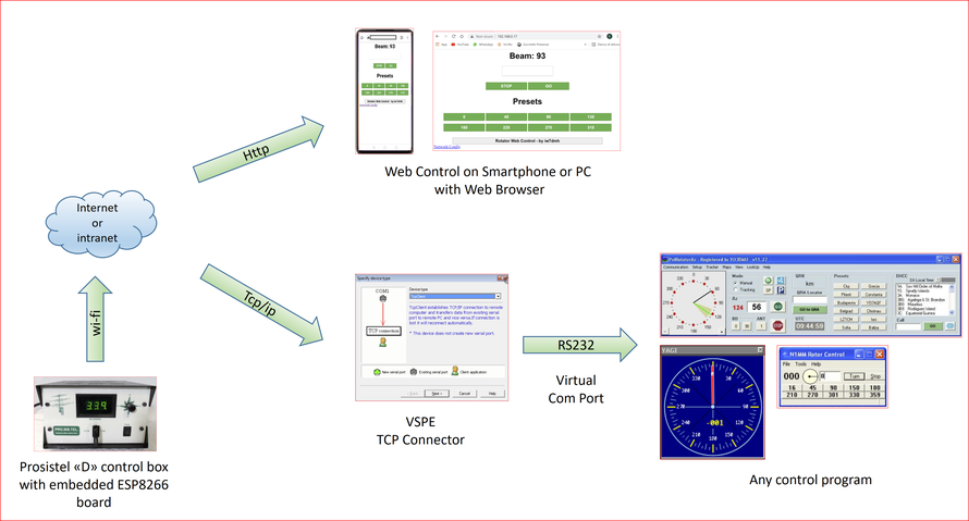
In this page I'll show you a simpler solution for a Prosistel "D" remote control system. It is a follow up of my two previous projects but this time isn't required any additional devices or dedicated software. For RS232 communication you'll need a virtual serial port driver so you can definitively remove the rs232 cable from "D" controller and computer. All data exchange will happen over wi-fi network.
The "big picture" is shown below.
Required Hardware
The required hardware is quite simple. All you need is a NODEMCU DEVKIT V0.9
and a TTL-RS232 level converter.

In addition I developed a small PCB with a simple 5V PSU Unit. In this way you can embed the whole system inside the control box.
PCB Schematics
I used the free Kicad EDA program. In the archive you'll find source files and PDF layout for direct printing solution.
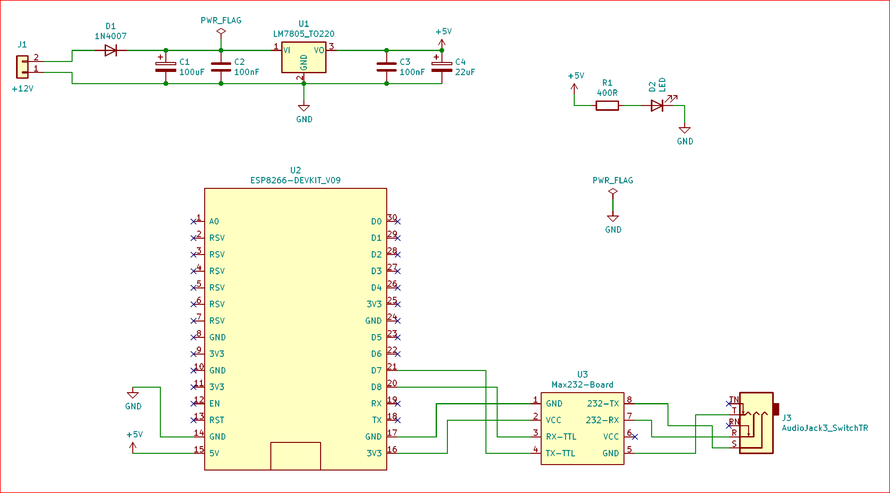

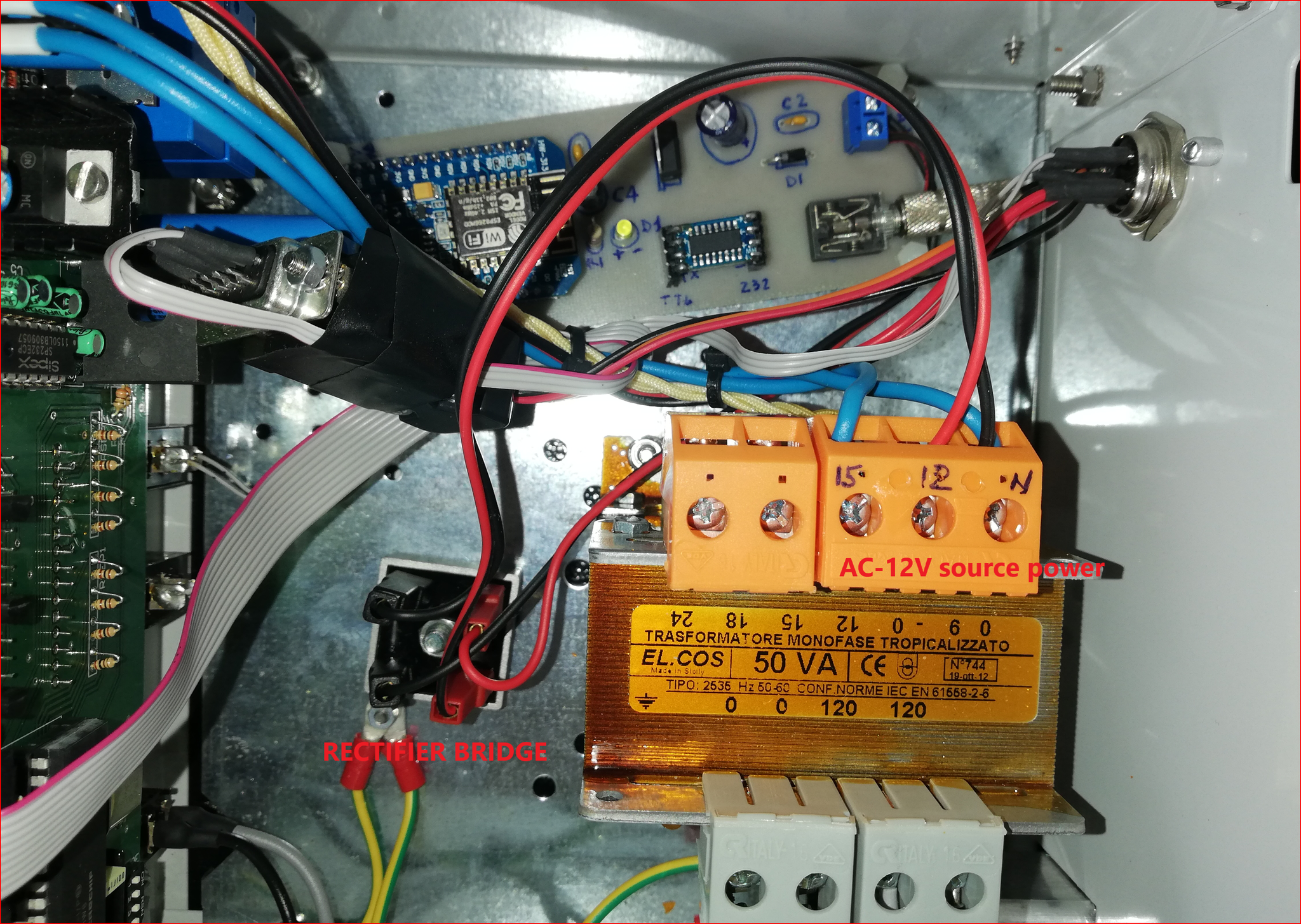
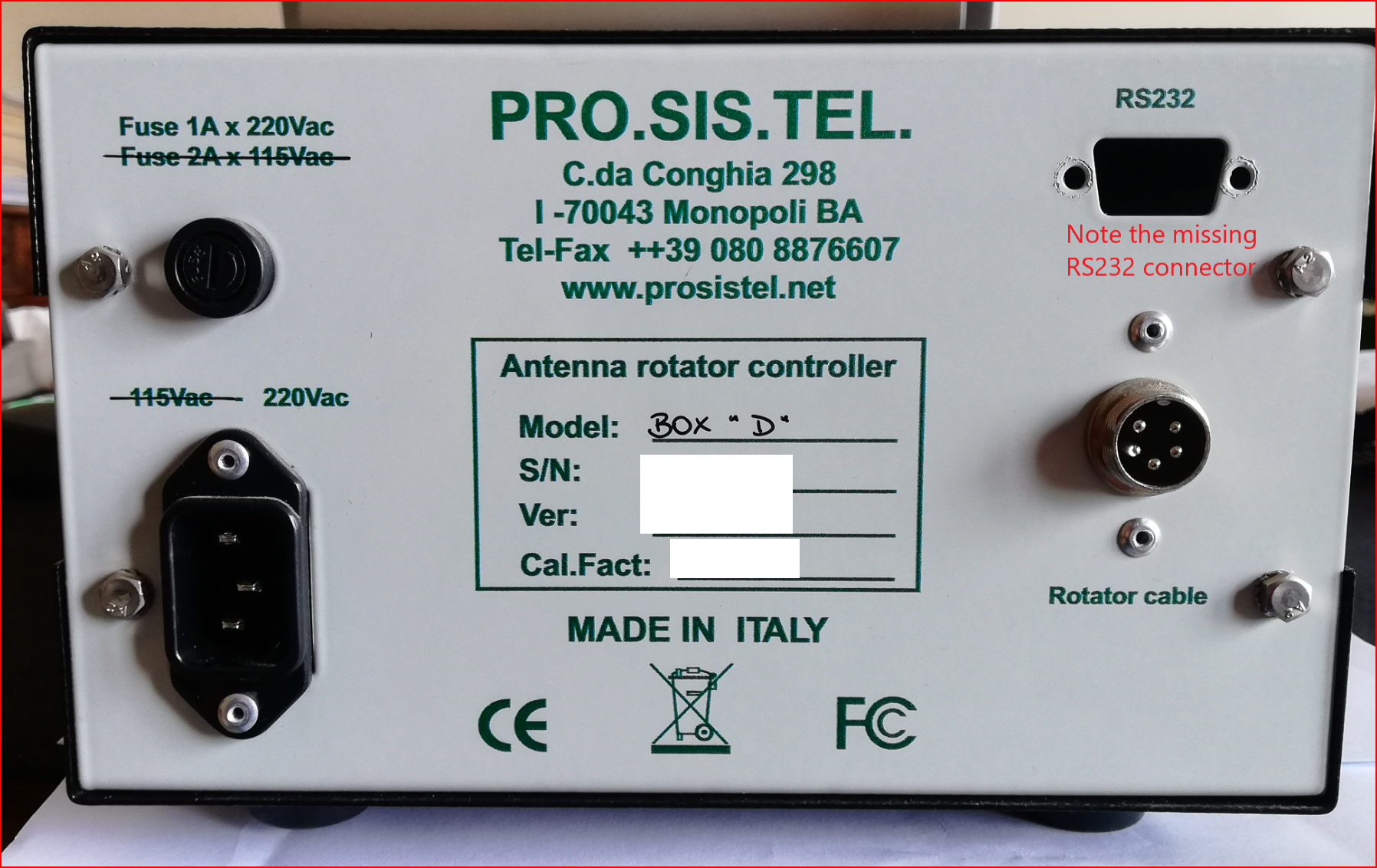
As you can see in the picture below, in the control box there is enough room to firmly install the PCB. To make the modification reversible I removed the RS232 connector from the back panel and used some adapters to connect the RS232 port. I didn't cut or unsoldered any of the existent cables or connections so I can revert back to the standard control box.
Please note the rectifier bridge I used to get the power from the original AC-220V-12V transformer.


Loading the firmware with NodeMcu Flasher tool
Now you have to load the provided firmware.bin file in your NodeMCU board.
It is a simple procedure using NodeMcu Flasher tool. Give a look at this video on how to do it.
Then power the controller up and start with the configuration procedure.
Configuration steps
1- Connect your computer or smartphone to the ROTOR-CONTROL access point that will appear after you power up the control box. See in the picture below

Now open the browser at the local address 192.168.4.1. If a password is required just type in 12345678.
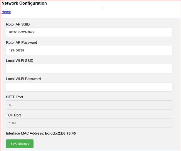
Simply configure the NODEMCU as shown below. You have to provide the following parameters:
- Rotor AP SSID - you can leave it unchanged
- Rotor AP Password - you can leave it unchanged
- Local Wi-Fi SSID - fill in with your local preferred access point
- Local Wi-Fi Password - fill in with the password required by your local access point
- HTTP Port - it is the port used by the web console (you can leave it unchanged)
- TCP Port - it is the port used by the Virtual Serial Port driver
In addition you may like to give a fixed ip address to the NODEMCU. Usually you need the network interface MAC address that is shown at the bottom of the page.
Once you have provided the required parameter just save settings and wait some second. The node MCU will restart and it will automatically connect to your wi-fi network. You sould be able to find the NODEMCU in the devices listed in your router.
Controlling from web page
Supposing you have fixed an IP Address like 192.168.0.17, you can access the web page opening the browser at the address http://192.168.0.17. In this example the HTTP port is 80 so you can omit it in the address, otherwise you have to specify it (for example http://192.168.0.17:8070).
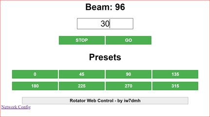
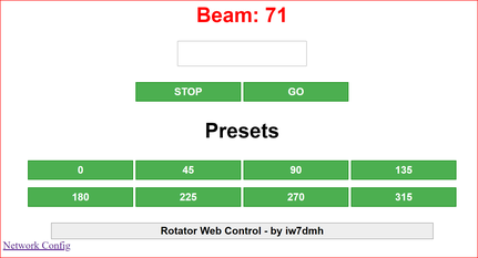
As you can see, the web console has some preset beams, but you can type any other beam in the big central text box. In addition, when the label bean is red colored, it means the rotator is moving. Click on the same label to get a refresh of the actual beam.
Controlling from computer
As previously stated you can control your rotator using any of the available programs. All that you need is a particular configuration of the VSPE driver. The only parameters you need are the NODEMCU IP address and the TCP port already configured in the previous steps.
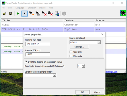
In the VSPE control panel configure a Connector (COM11 in the example below). Then add a TCP Client as shown in the second picture.

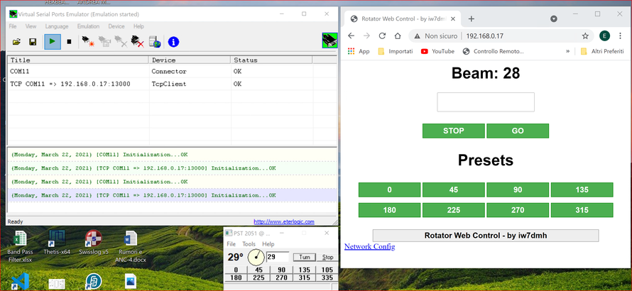
Now you can control the rotator with other programs like N1MM rotator. Consider that the web console is always available even if the rotator is controlled by another program as shown in the picture below.
I hope you'll enjoy this project.
Best 73'
Enzo, iw7dmh