63.5 dB Programmable Digital Attenuator
Looking on Internet for a fixed RF attenuator I found a nice one based on the Peregrine PE43702 chip. From the datasheet I read the PE43702 is a HaRPTM-enhanced, high linearity, 7-bit RF Digital Step Attenuator (DSA). It covers a 31.75 dB attenuation range in 0.25 dB steps in the frequencies between 9 KHz - 4.0 GHz , has a 50 Ohm impedance and provides both a serial and parallel CMOS control interface. I immediately thought about a Arduino controlled device and decided to use two of them cascaded.
The pictures below are taken from the online seller.

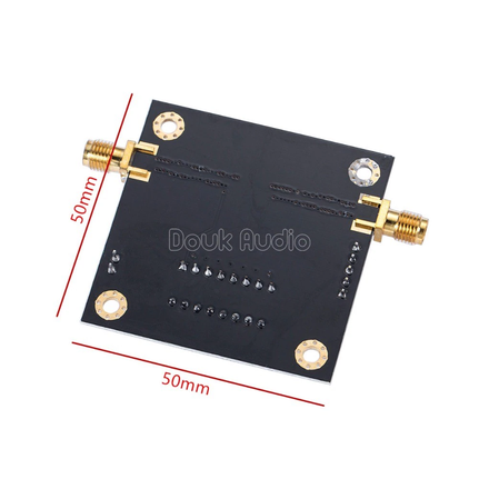
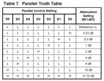
The breakout board provides a parallel dip-switch for manual usage. In such a case you only have to provide 5V power supply through the dedicate connector and set the P/S switch to OFF (Pin #1). Then you can set the attenuation level using the other seven switches as described in the following table
In my project I used the serial interface setting the attenuation level through code via the SPI protocol. In the serial configuration all the parallel dip-switches have to be OFF except for the P/S switch that is set to ON (Pin #1). Power can be supplied through the V+ and GND pins on the SPI connector.
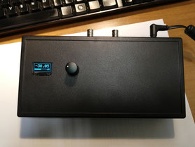
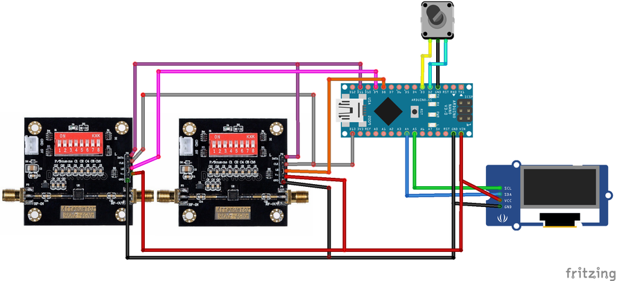
To make things simpler my device provide a small rotary encoder and a display to change and view the attenuation level as shown in the schematic below.
Some measurements
Before going on with the code it is important to understand the return loss response on the various frequencies. I did some measurements using my NanoVNA-F configured like in the picture below.

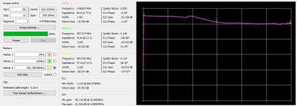
The left picture is a measurement on the range 10 KHz - 1 GHz @ -20 dB attenuation level. As you can see the response is almost linear in the range 0.1 - 200 MHz and in the range 0.5 - 1.0 GHz. In the middle the response is not very good but I wouldn't be surprised if the chinese VNA should have some issue or (undocumented) limitations.
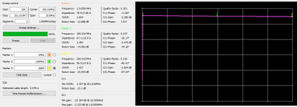
In the right picture I measured the response in the range 10KHz - 200 Mhz @ 0.0 dB attenutation level. It is the frequency range I am most interested in. Responce here is nicely flat and, as stated in the datasheet each PE43702 chip has a fixed loss of about 1.25 dB. This is a mean of 2.55 dB for the two cascaded modules. I will use this value to display the actual attenuation level in the display.
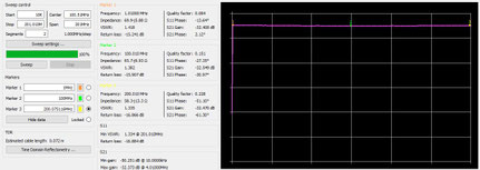
Below are the same range measurement at different attenuation levels: -10 dB, -20 dB, -30 dB, -40 dB, -50 dB, -60 dB. In the last two measurement I think I am hitting the NanoVNA measurement limits. Maybe the actual response is better then that shown.


Code
Code is very intuitive and you can download it from my DropBox space. In the Attenuator.ino file you can find the pin definitions.
Note the ATT1_SS_PIN and ATT2_SS_PIN that are used for the SPI chip select logic and the SPI.setBitOrder(LSBFIRST); statement used for a proper protocol configuration. You can find all the other details in the datasheet.
The more interesting part is in the file SPControl.ino: the cascade modules works almost in pair.
When the requested attenuation level is below 31.75 dB only one chip is enabled while the other is in bypass mode. When the requested attenuation level goes over 31.75 dB one chip is enabled at the maximum level and the other is enabled at a value of Total Attenuation level - 31.75 dB.
The rest of the code is a matter of input/output handling routines.
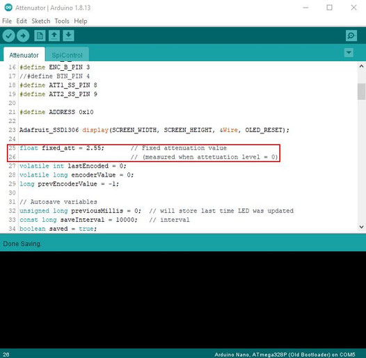
N.B. One thing to remember is to set the fixed attenuation level in the code (line #25 - see the picture below) before you program the Arduino. Of course you have to do measurements on your chip.
Building
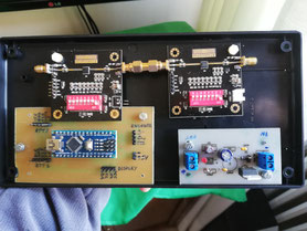
Building the circuit is not my favourite practice. Anyway you can see my "patchwork" building. I reused a psu board and a very big plastic box. Also the encoder and the display came from the junk box. Not so bad in the end.
I hope you'll enjoy the article.
best 73'
Enzo, iw7dmh